Projects Links

Click on the "Links"  to go to Project and About Pages Click for Projects Links                                 About the Vess...

Saturday, August 13, 2016

Windlass Installation


For the last year I have been mulling over the idea of installing a windlass.   I have had my eyes on a Lewmar V2 5/6” G4 as the prices were reasonable ($1.5k) but recently I found the Maxwell RC-8-8 (from my understanding a much better windlass) online for an unbelievable price: $1,048 with free shipping from TheDigitalOasis.com.  This windlass normally goes for about $2k.  So I ordered it, and it shortly arrived in a factory sealed box from Maxwell.  But before ordering,  I called Maxwell support and asked them if there where any problems or plans to replace the RC windlass.  They said that the RC is one of their best devices with no plans to replace the line, but that they were aware of some retailers having aggressive pricing like Defender.

For additional equipment,  I went 150’ 5/16” G4 HT chain, 150’ 5/8” 8-plait nylon rope, Mantus SS swivel,  and 44lb Vulcan anchor.   Also I read good thing about using a 4WD winch controllers on a marine windlass, so I picked up both a wireless remote and wired remote( and socket) winch controllers from amazon. The wireless controller works great but does have a slight delay which the wired controller does not.


Maxwell RC8-8 windlass


MAXWELL RC8-8 SPECIFICATIONS
Model

RC8 8mm - 5/16"


Maximum Pull

600kg
1320lbs


Static Hold

1200kg
2640 lbs


Chain Short Link

8mm
5/16"


Rope Size
(3 strand or 8 plait)


14mm-16mm
9/16"- 5/8"


Chain Speed
(Normal working load)


32m/min
105ft/min


Rope Speed
(Normal working load)


28m/min
92ft/min


Power Supply (DC)
12V


Motor Power
1000W


Net weight DC Low profile version

16.5kg
36.3lbs


Planning

The plans was to install the windlass directly over the bulkhead separating the v-berth and the anchor locker so that the deck chain hole is over the anchor locker whereas the windlass drive hole was over the v-berth.  The advantage of doing it this way is that the windlass motor, drive unit, switching solenoid, and all electrical connections are protected from saltwater and weather.  It turns out that the space between the two holes is almost exactly the width of the bulkhead leaving little to no room for error.

The location of inside bulkhead was transferred to the deck using two strings.  Within the v-berth access, a string was stretched from the center of a bow cleat bolt to the center of the opposite bow cleat bolt, one string topside and the other inside (see picture below).  An identical string was stretched on the deck from the tops of the same two cleat bolts.  Measurements along the string and perpendicular to the string where easily transferred from inside to topside.  This allowed for a somewhat precise determination of the bulkhead location which was drawn in pencil onto deck.  The Maxwell mounting template was placed by aligning it fore & aft so that the bulkhead was aligned with the template gap between the two hole cutouts. The port & starboard location (i.e. direction along the string) was determined by aligning a straight rode from the left bow roller with the rode location as indicated on the mounting template.


A view from within the v-berth, a string was
stretched from the center of a bow cleat 
bolt to the center of the opposite bow cleat 
bolt.  Measurements along the string and 
perpendicular to the string can be easily 
transferred from inside to topside.
RC8-8 deck cutout & holes details. Note: the cutout marked
as "B" is not required unless one plans to connect a chain
link counter.


Final placement of the mounting template.  Also shown is the
topside alignment string and a tape with a center line indicating
the proper parallel rode direction coming from the left bow roller. 


Drilling holes in the Deck

Measure many times, and cut holes once became the crucial plans.

Chain hole was drilled with a slight
angle from aft to fore.  
Partial hole as seen from inside anchor
locker looking up.


Drilled hole into anchor locker
Preparing for cutting the windlass drive hole.
View of the roller furler from
v-berth up through the windlass
drive hole. 


Dry Fitting the Windlass


Deck placement of the windlass.
A view of the chain drop hole aligning
with the windlass during the dry fit.


Dry fit of windlass without drive unit. 
Dry fit of windlass with drive unit.  


The forward bolt hole interfered with the
anchor locker bulkhead. Part of the
bulkhead was carved out to provide room
for the mounting bolt, nut, and washer.
This areas was later sealed with epoxy.
Dry fit of windlass with drive unit.  A 
little bit (~3/16"x2"x2") of  the bulkhead was removed 
with a Dremel sanding drum out to provide
 clearance for drive unit. This areas was 
later sealed with epoxy.


Sealing the Deck Core


Removing/Reaming the balsa coring with a Dremel sanding drum.
Over sized bolt holes were first
wetted with epoxy, filled epoxy
thickened with colloidal silica,
and after curing, redrilled to
proper size.

Sealed coring with first an application of wetted epoxy before
filling reamed area with epoxy thickened with colloidal silica .
East System epoxy and colloidal silica
obtained from Noah's Marine.


Mounting the windlass

Deck masking for easy removal of excess
sealant.   

After masking the windlass outside and chain drop inside, lots
of sealant was applied for the deck mount.  An abundance of sealant
is needed to provide a watertight seal so that water does not enter
into the v-berth.   A paper towel & white tape was used to cover 
the Super-Lube greased drive shaft during installation so that no
grease contaminated the sealant surfaces.


Windlass motor and drive unit.
Install without the backing plate initially to set the sealant
and form a nice gasket seal. 


Installed with 3/4"epoxy sealed marine plywood backing plate.
The backing plate also provides mounting surface for the
solenoid switch junction box.


Electrical Wiring

I originally planned to use 0 AWG battery cable, but ordered 1 AWG.  To get a better than 0 AWG equivalent, I added 4 AWG in parallel for the long runs to the solenoid switch.

Windlass wiring schematic


The switching solenoid unit .
Working installation.


Finishing the Installation


Reinstalling the v-berth headliner.


V-berth with windlass cover box. Bottom panel has a vent
to promote airflow and easy inspection.
Feeding 150' of 5/16" G4 HT chain.   A future plan
includes mounting a stainless steel protective sheet
under the chain run of the anchor locker lid.

Several months after installing the windlass
and stainless steel plate was add to the anchor
locker lid at the location of greatest chain wear.


Remote Windlass Controls

I am not a big fan of the commonly used foot switches for controlling a windlass.  Not only does it mean cutting additional unnecessary holes in the deck, these switches are know to fail due to the harsh saltwater environment.   Instead I chose to install a wireless remote system commonly sold for off-road vehicles (Trucks, Jeeps, ATV).  These systems are standardized, pretty robust, easy to install, and amazingly affordable at under $15 Amazon Prime.  The unit I purchased came with a standard hand-held remote and a second mini keyring remote.  To install connect 4 wire: red & black for 12V power and white & yellow for up & down control.  A 5th wire is the antenna for the remote box.

I carelessly dropped the remote overboard during my first week of use and retrieved it as it remained floating.  A quick fresh water rinse and all was fine. UPDATE: After 5 years of use, the wireless remote system remains working perfectly.  Since the first drop overboard, I have been more careful and have not done so again.  The remote works from anywhere on the boat (50ft range claim).  I often use it single-handing from the cockpit to the bow.  I cannot say enough good things about it.  6 out of 5 Stars.


DC 12V Black Wireless 50FT Remote Control Kit for Car Truck Jeep ATV Winch Tuff Stuff keychain remote Warn Ramsey Gorilla Bulldog Latest Long range model Indicator light Universal as listed on Amazon for $14.49.


As a back up, I installed a CSI W130 Winch Remote and CSI CSIW261 Remote Control Socket.  The socket was installed in the v-berth.  To operate, the wired remote is led out to the bow through the v-berth hatch.  I have used it one to test it out and have not need to use it since.  Ironically, the wired system cost me $20 more than the wireless system.  I view the extra as insurance.


The above photo show the CSI socket and the CSI W130 Wired Winch Remote with 12' cable.

Tuesday, March 15, 2016

Installing and Bedding Deck Hardware

Cleat Installation

 This deck cleat, mounted by the mast winches, was previously screwed on the cabin top with stainless steel oval head screws.  There are a few places where using screws would be acceptable, but cleats should be through bolted with proper backing plate or wide fender washer backings.  This cleat was removed and the screws hole filled with thickened epoxy prior to the repainting of the deck.  Below is the description of properly reinstalling the cleat with 5/16" stainless steel oval head bolts.


Preparing the bolt holes

 3/4" flat-blade wood bit
After marking the bolt hole center locations, a 3/4" flat-blade wood bit was used to over drill the bolt holes removing the top fiberglassed layer and the deck coring.  Care was taken to drill the hole deep enough to just remove the wood coring but to leave bottom fiberglass layer intact.  

If the deck hardware was already through bolted, but with bolt holes that exposed the core, these holes should have been prior filled with thickened epoxy along with a proper cleaning of the surfaces removing all traces of the old sealant.

If the coring is wet or rotten it should be removed by reaming the material out and letting it dry.  Soaking the wet core with alcohol aids in water removal and drying.  This is because both are highly soluble in one another and with a higher alcohol to water concentration the vaporization temperature of alcohol is much lower, so the alcohol/water mixture evaporates much quicker.


Over drilled holes remove core material exposing clean dry core.

Filling the bolt holes with Epoxy

Over drilled holes wetted with epoxy. 
Before filling the holes with a thickened epoxy mixture, always wet the hole and remaining core surface with un-thickened epoxy.  Start off by mixing a batch of epoxy resin and hardener. Throughly wet all inside surfaces with the epoxy.  Gently heating the surface (not the epoxy) with a heat gun prior to applying the epoxy helps the wet epoxy soak into the core.  With the hole not going completely through the bottom layer(tap the underside if there is penetration), the hole can be completely filled with epoxy then extracted (after 20-30 seconds) with a syringe leaving behind a throughly wetted surface.  Alternatively, throughly wetting with an epoxy/acid brush also works well.  After soaking the surfaces, the brush can be used to wick up excess epoxy.

Over drilled holes filled with thickened epoxy.
Next, thicken the epoxy with colloidal silica to a mayonnaise consistency.  Completely fill the holes with the thickened epoxy.  The advantage to having on oversized hole is that it is easier to fill the hole with thickened epoxy without leaving trapped air bubbles.  Any remaining air bubbles can be removed by mixing the thickened epoxy in the holes with a small wire (like a straightened paper clip).  An alternative is to gentle heat the epoxy mixture.  This will temporarily make the mixture less viscous and allow it to flow nicely filling up the hole.  Don't over heat the epoxy mixture as it can prematurely kick-off the epoxy.

After the epoxy kicks and while it is still green (hard but soft tacky surface ), the top deck surface with thickened epoxy can be easily cleaned up and trimmed flush otherwise a Dremel with a sanding drum does a nice job of trimming the thickened epoxy when fully cured.
 
Bedding the hardware

Deck cleat properly bedded with Bostic 940FS.
With the thickened epoxy cured, mark the centers for new drill holes aligning the new center marks in the center of the previously filled holes.  Drill the proper sized bolt holes through the center marks and chamfer the holes with a countersink bit.   When bedding, the chamfer provides an area for the sealant to form a gasket around the bolt.

Apply sealant to the underside of the hardware and spread evenly then insert the bolts in the hardware and apply a thick ring of sealant on the top of bolt treads and underside of the hardware.  Now insert all hardware bolts in the holes and simultaneously push down the hardware and bolts.   Now from below, fit a backing plate or use fender washers and snug the nuts by turning the nuts only and not the bolts.  Don't over tighten them.  This will allow the sealant to push out and form a gasket.  Over tightening is bad as it will push out too much sealant limiting proper sealing.  After the sealant has partially cured, tighten down the nuts without moving the bolts.  This is much easier using nuts with separate lock washers rather than the nuts with built-in nylon lock inserts (i.e. nylon lock nuts).

Now for a word on sealant.  Butyl tape works well for bedding hardware, and there are many online references attesting to this.  While I have used butyl for some hardware bedding, lately I have come to favor using Bostik Marine 940FS adhesive/sealant for several reasons.  For one, my marina keeps it in stock at a very reasonable price.  But more importantly, it has performed extremely well.  It also skins over and partial cures in about 30 minutes.  This allows me to bed the hardware, complete the tightening of the hardware,  and clean-up with an hour.

Here is a description of 940FS from the Bostik website:


Bostik Marine 940 FS is recommended for use in bonding and sealing applications, particularly where permanent elastic bonding between surfaces is required. It can be used above and below the waterline. Its outstanding adhesion and UV resistance properties target this product for sealing deck hardware, through-hull fittings, rub-rails and portholes applications.


Newly bedded cleat in use.


DYI Galvanic Isolator

Isolation of Galvanic Voltages (A self inflicted problem)

The main purpose of Galvanic Isolator is to provide isolation from galvanic voltages which result from bonding the AC and DC grounds.  The reason for connecting the AC & DC grounds is to provide an Effective Ground-Fault Current Path from the DC ground to the AC ground.

But in principle, the AC to DC ground connection, and thus a Galvanic Isolator, should not be needed since GFCI( also called ELCI or RCD) protection should be used for all vessel AC loads.  This can be accomplished for the whole vessels by installing an ELCI Main Circuit Breaker such as a BlueSeas model 3106100. In fact, the ABYC E-11 now requires all new vessels to have such a device. An  ELCI/GFCI detects ground-faults and disables the circuit.  Disabling a ground-faulted device by eliminating the power source is much safer than just providing a safe effective ground-fault current path.

Many small and older sailboats do not suffer from galvanic corrosion.  The reason is that these vessels often do not have their AC & DC grounds connected.  If a vessel has only a few AC outlets, then the likelihood of an AC to DC ground-fault is rather small.  Typically on these vessels only a battery charger is interfaced to both AC and DC power systems.  But any decent marine battery charger should be built to ABYC / UL 1236 standards which require isolation of AC & DC (i.e., Don't use cheap chargers).   In any case, one GFCI outlet can protect the whole boat from ground faults making the vessel ground fault safe without the necessity of connecting DC and AC grounds.

So why connect the AC and DC grounds if ELCI/GFCI protects the vessel from ground faults?  To be honest, there is no good reason.  Famed boat guru Nigel Calder advocates against connecting AC and DC grounds.  And new standards no longer require AC to DC ground connections when the "whole-craft" is ELCI protected.  See IOS 13297 excerpt below.

A possible reason given is because of the "other guy".  That is, electrical problems which originate external to (i.e. outside) one's vessel.  These are problems due to faulty or incorrectly wired shore power or poor/faulty electrical systems on neighboring vessels.  While GFCIs can protect a vessel from self ground faults, unfortunately a GFCI will not protect against external faults.  No one wants to work on an engine and end up being the conduit to ground for a stray neighboring current.  In this case, an AC to DC ground connection can provide protection (unless one is removing the engine ground in which case an AC to DC ground connection could be harmful).

Given all of this, it does not make much sense to spend a lot of money on a Galvanic Isolator.  But rather, invest in an ELCI Main Circuit Breaker.  These devices cost less than most Galvanic Isolators.  If one does connect the AC & DC grounds then one should make this connector through a basic Galvanic Isolator like a Yandina (or DYI device like the one described below) since this type of connection, opposed to cutting and inserting into the AC "green" ground, does not compromise the vessel AC ground fault safety, that is a fail-safe connection.   A good DYI Galvanic Isolator is easy to make and cost relatively very little (~$10).   The DYI Galvanic Isolator shown below was made with free scrap material costing only $5.60 for the rectifiers.


Components
Bridge Rectifier
  • (2) Bridge Rectifiers 
    • 50A 1000V Metal Case Bridge Rectifier with Heatsink  
    • KBPC5010
    • Amazon: $2.80 each w/ free shipping
  • length of green wire & solder
  • (2) crimp-on ring connectors
  • (2) 1/4-20 SS bolts for wire terminal ends


Component & Circuit Description

First grab the rectifier and identify the "+" terminal.  This terminal is marked with a "+" and is oriented at right angles to the other three.  Diagonally across from the "+" terminal  is the "-" terminal.  The other two terminals are the AC terminals sometimes marked with a "~".  The "~" terminals are not used and are often best cut off to make it easier for making wire connections and eliminate installation mix ups or later shorting out.  

Below is the circuit diagram.  Shown are the two rectifiers connect by wires.  The arrows show the direction of current flow. Each rectifier connection only lets current to flow in one direction.  The two opposite rectifiers allow current flow in alternating direction (i.e. AC).   But current can only flow when the voltage exceeds ~1.2 Volts (twice the forward bias voltage of single  diode). Since galvanic voltages are well below 1 Volt, galvanic DC currents are blocked whereas AC currents are not.


Circuit Assembly

The diagram shows the input and output green wire connected in the middle of a wire connection of the (+) & (-) of each rectifier.  In fact, it is easy to use one long wire (~ 1ft) on each connection.   A stripped wire end can be tightly wrapped through and around the (-) terminal while the (+) terminal connection can be made by stripping out an inch of insulation from the wire just a little way from the (-) end (without cutting the wire) and wrap this bare wire tightly around the (+) terminal leading remaining wire out.   To further secure the mechanical connection, the wire can be soldered at the terminals.   Alternatively, crimped spade connector connections should also work fine for making wire connections.


Circuit diagram: The arrows show the direction of current flow. Each rectifier connection only lets current to flow in one direction.  The two opposite rectifiers allow current flow in alternating direction (i.e. AC).   But current can only flow when the voltage exceeds ~1.2 Volts (twice the forward bias voltage of diode). Since galvanic voltages are well below 1 Volt, galvanic DC currents are blocked whereas AC c currents are not.


Making a simple housing  container 


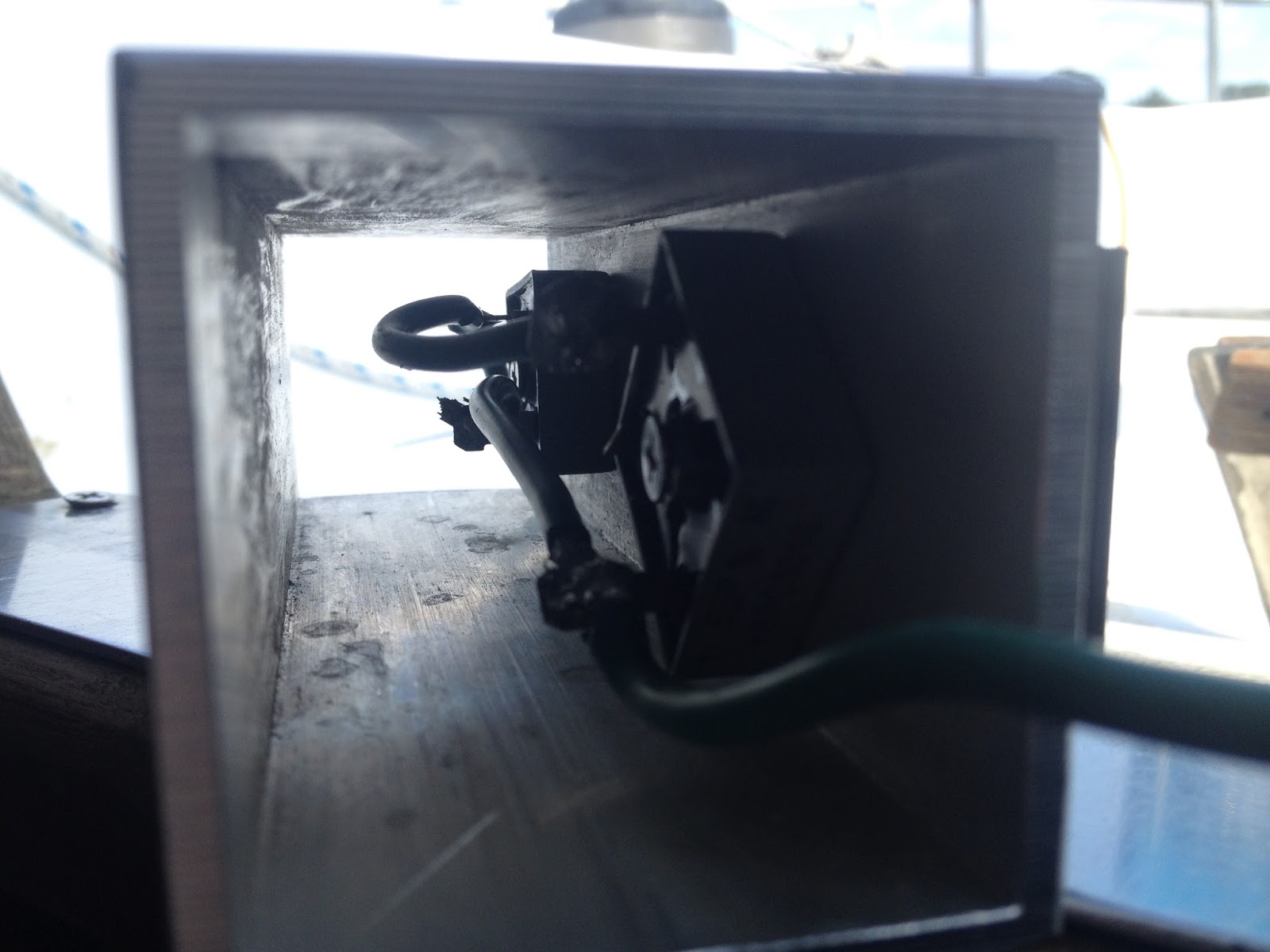
With the galvanic isolator circuit complete, a simple housing box can be fabricated using a scrap piece of square aluminum tube.  Each rectifier can be bolted to the inside and to the heat sink on the outside.  The green wires can be led out the ends and through a simple end caps made of HDPE.  A bolt can be added top each end cap to form connection terminals, and a crimped on ring connection can be added to the trimmed green wire ends and connected the end bolt terminal.  Alternatively, one could use a prefab housing box or even a simple piece of round tube or right angle extruded aluminum. 

Aluminum allows for efficient heat transfer.  But normal operation does not generate heat.  Heat  is only generated if there is an actual ground fault.  In principle, the circuit can operate at currents higher than a 30AMP shore power supply.   But one should also be using GFCI circuit protection which would cut the power if a ground fault exists.   


DYI Galvanic Isolator prior to installation.


A Fail Safe Galvanic Isolator Installation

First off, it is important to use a decent marine battery charger and not a cheap $10ish charger.   All AC loads on a vessel should be GFCI protected, and even better use in addition, an ELCI Main Circuit Breaker in the main AC panel.   Then install a Galvanic Isolator  between the DC ground and the AC ground and not by cutting/installing in the AC green ground line.   This arrangement provides redundant protection mainly via the total GFCI protection and additional safe guards of galvanic isolated AC/DC ground fault path while not breaking the wire or adding components in series to the AC ground fault line.


Extract from ISO13297

4.2 The protective conductor (AC Earth) shall be connected to the craft's d.c. negative ground (earth) as close as practicable to the battery (d.c.) negative terminal.
NOTE If an RCD (whole-craft residual current device) or an isolation transformer is installed in the main supply circuit of the a.c. system (see 8.2), the negative ground terminal of the d.c. system need not be connected to the a.c. shore ground
(protective conductor).


Monday, March 7, 2016

Paragon SAO V Transmission Adjustments

A few months after getting Johanna Rose back into the water, I started to notice a problem with the transmission slipping and thought that I needed to have the transmission rebuilt.  I called Transmission Marine, Inc in Fort Lauderdale and spoke with one of the Paragon experts about a rebuild.  While I received the info on a complete rebuild, I was encouraged to adjust the clutch plates myself first. I received quick instructions over the phone, and later found a nice description online.  Much of the Paragon transmission adjustments described below were provided by Ralph Mudge on the CnC mailing list on Apr 18, 2009.   It turns out that my forward transmission slippage was partly due to a miss-adjustment of the transmission cable causing the transmission to not fully engage (or click) in forward.   My problem was corrected by properly adjusting the transmission cable and by tightening the forward clutch adjustment in the transmission.  At the same time, I adjusted the reversing band. After a year and half and about 50 hrs of engine use later, all still seems fine with the transmission. 

Adjustment of the forward clutches 
Remove the 4 bolts that hold the top cover down and take off the cover. 
(Try to save the gasket, but new ones are cheap)  As you look down into 
the guts, there is a fore and aft shaft that goes through the clutch pack 
that has a castle nut on the end( about 1-1 1/2 ").  With the transmission 
in neutral, turn that shaft with a screwdriver until you find a locking bolt.  
Back off the bolt until you can turn the castle nut.  Careful, a small adjustment 
goes a real long way and there is no frame of reference as to how far 
you have turned it.  In your case, I would try turning it only 2 
notches.  In other words, from the locking bolt turn the nut 
clockwise(facing aft) 2 indentations in the nut (for the locking bolt), 
and lock it down again.  Try it out.  If you have gone too far, the prop 
shaft will slowly turn over in neutral,  meaning that the clutches are 
not fully released. Back up one notch on the nut a try again.  (Though 
neutral is kind of a moving target on this transmission)  If you still 
have slippage, you have not gone far enough, try turning the nut one 
more notch.

Adjustment of the reversing clutch or band
With the top cover off, as you face aft, on the back left side of the 
gearbox, there is a largish nut with a spring clip around it.
Turning that nut clockwise will tighten the band.  Again, small 
adjustments!  One or two flats on the nut make a significant change. 
This will move the reversing movement closer to the neutral spot on the 
shifter, in other words you will not have to push so far down on the 
shifter to fully engage reverse


Top view of Paragon transmission
with top cover removed.


Top cover for Paragon SAO V Transmission


The reserving band adjuster is the horizontal part at the top of the photo
which has holes in the broad bolt-head and goes through the spring. The locking
bolt for the forward clutch adjustment is shown in the center of the photo.   


Transmission Oils
The folks at Transmission Marine, Inc in Fort Lauderdale, recommended the use of ATF or 30W in the paragon and 30W non-detergent oil in the Walter V-drive.  The advantage of ATF is that the fluid provides less drag for the clutch plates in neutral whereas with 30W in the Paragon, the drag can lead to minor turning of the prop shaft while in neutral.  Unfortunately, there are many types of ATF, and some types may actually lead to premature clutch plate slippage.  Because of concerns with transmission slippage, 30W non-detergent is used in both the Paragon transmission and the Walter V-drive.  An added plus is that one only needs to keep one type of transmission oil on hand.