Projects Links

Click on the "Links"  to go to Project and About Pages Click for Projects Links                                 About the Vess...

Friday, November 20, 2020

Ham Radio Set Up on a Sailboat


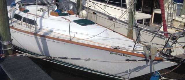
Yaesu FT-981 on a 38' Sailboat 

HF Transceiver

FT-891 remote head unit
The HF radio system on Johanna Rose consists of an amatuer radio HF transceiver, a split backstay antenna, an antenna autotuner, and a RF coupled ground system.  The HF transceiver is a Yaesu FT-891 The Yaesu FT-891 is a HF/50MHz all mode mobile transceiver with 100W of transmit power.  Yaesu is one of the world leaders in radio transceivers.  I considered several other radio options, but the FT-891 is a great performing radio with extended capabilities and function  and ended up being the best value in today's market.   The radio is powered via the 12VDC house battery bank via a 25A breaker.   The detachable front panel of the FT-891 was mounted on a bulkhead by the campanionway in the aft cabin area.  The main transceiver was mounted a short distance away high up in the portside quarter berth area. 

FT-891 base unit, Signalink unit,  and Raspberry
Pi4B computer.  Also shown is the DIY remote
control for the SG-239.


Antenna & Ground/CounterPoise System

RF ground coupler
(7@0.1 uF capacitors)

SGC SG-239 auto-tuner mounted
in weatherproof enclosure inside
the transom
The stainless steel backstay is uses as a long random wire antenna.  A Sta-Lok backstay insulator was installed about 45ft up the stainless steel backstay.  The bottom of the backstay connect to a chainplate which is bolted internally to a fiberglass support-knee in the transom.   I considered several autotuner options, but after reading many reviews, I went with the SGC SG-239 auto-tuner as it has a great reputation, great price, but more importantly it can be mounted at the antenna base and monitored/controlled remotely.  The  SG-239 was installed in a weatherproof enclosure mounted in the transom.  A RG-58 cable with PL-259 connectors connect the FT-891 to the SG-239 auto-tuner.   The auto-tuner antenna output is connected to a chainplate bolt using a 5 inch 10AWG wire and ring terminals.  The auto-tuner antenna ground uses a 1-1/2inch tinned copper braid connecting the SG-239 to a bronze seacock through a RF coupler providing a RF pass but DC block.  The RF coupler was made by cutting the copper braid just before the bronze seacock and reconnected the two end via a block with 7 capacitors in parallel (0.7 uF total capacitance).  


RF grounding to seawater via bronze seacock.

Auto-tuner antenna output to backstay.


Backstay with antenna insulator ~4' from top
Sta-Lok insulator installation


Digital Communication Devices

Digital communications, including sending and receiving SSB emails requires either an expensive hardware modem or a computer sound card and software to provide modem functionality.  The latter has come about from rapid advances and community development in the Ham community.  While software equivalent modems do not yet have the same data transfer rates as the latest Pactor 4 modem, the gap is rapidly narrowing.  This is quite remarkable given that a P4 modem coast over $2,000 whereas the software equivalent, the cost of an external USB computer sound card goes from $10 to $100.  For digital communications, I use a Signalink USB SLUSB6PM isolated sound card.  I have also used a $7 external USB sound card purchased from Amazon with a home-made interface cable.  While the cheap sound card works well, the simplicity and the dial controls of the Signalink, make it a simple to set up, adjust, and utilize.

main component list

  • Yaesu FT-891 Transceiver  ($510 w/ rebate Gigaparts)
  • SGC SG-239  1.8 - 30 MHz 200W PEP  Smartuner ($174 open box R&L Electronics)
  • Signalink USB SLUSB6PM ($97 Gigaparts)
  • Grounding Counterpoise via 1-1/2" tinned copper braid w/ RF coupler
  • Sta-Lok 5/16” 1x19 SS316 wire backstay insulator  ($225 Offshore Spars) 
  • Raspberry Pi 4B 4GB ($55 )
Total Cost: ~$1000 


Wednesday, November 18, 2020

Amateur Radio FOX Hunt Transmitter

Fox hunting is an activity in radio transmitter hunting in which the hunters use radio direction finding techniques to locate a radio transmitters (the fox) which is hidden within a designated search area. 

This activity is most popular among amateur radio enthusiasts, and one organized sport variation is known as amateur radio direction finding.

Constructing an Arduino Uno/BaoFeng  Fox Transmitter

Hardware Components 

  • BaoFeng UV-5R
  • Arduino Uno
  • 5V One Channel Relay Module Relay Switch with OPTO Isolation High Low Level Trigger
  • BAOFENG Speaker MIC for BAOFENG UV-5R 
  • Enclosure box for Arduino Uno & Relay 
  • 18650 Battery Holder with Leads with common 2.1mm DC power plug 
  • three 18650 Lithium-Ion 3000mAh Batteries
  • SMA female to SMA male 12" cable
  • SMA female to female connector
  • Plastic Ammo Box 


The Completed FOX Transmitter

The Fox Transmitter is housed in a plastic ammo box obtained from Harbor Freight for $2.99.  An SMA male to male connector is mounted on the ammo box lid.  An SMA female to female connector connects the BaoFeng antenna to the ammo box.  In the pictures shown, SMA to BNC, BNC to BNC, BNC to SMA connectors are used.   This would allow for remotely mounting the antenna using a BNC cable. To provide the internal antenna connection, a 12" long SMA female to SMA male cable connect the external antenna to the BaoFeng UV-5R.   A piece of hard foam was placed inside the ammo box with cut outs for mounting the BaoFeng and the Arduino box.


Fox Transmitter.  Note: can be locked
with a common padlock.
 

Fox Transmitter main components
consisting of a BaoFeng UV-5R and
an Arduino with Relay Module.
Main components shown with Arduino
battery pack mounted to enclosure.  To
operate Fox, insert Arduino power plug
 and turn on the BaoFeng UV-5R.  


Power Pack Construction
The FOX transmitter uses the built-in BaoFeng battery for normal HT operations.  The Arduino is powered by 3 18650 Lithium batteries (I used Sony/Murata VTC6 18650 3000mAh).  The batteries were connected in series using a 18650 battery holder purchased from Amazon (2 holders @ $6.99). The battery holder wire leads were connected to a common 2.1mm DC power plug which was cut off from end of an old 9V AC/DC power adapter.   The three 18650 batteries provides 3000 mAh at 10.8 V which is enough power for over 8 hrs of operation.  In actual use, the BaoFeng battery drains before the Arduino battery pack.  Note: the Arduino Uno maximum power consumption is 5V@800mA giving  (3000 mAhrs)*(10.8 V)/(5 V)/(800 mA) = 8.1 hrs.   Also, it is trivial to quickly replace the BaoFeng or 18650 batteries with spares. 


Arduino & Relay Enclosure Construction
The Arduino Uno and the Relay Module were mounted using nylon screws to a 4"x3" piece of 1/8" clear acrylic.  The acrylic was then mounted using VHB tape to a metal enclosure box of interior dimensions 4-1/2" x 3-1/2" x 1-1/8".  Two holes were drilled in the enclosure box.  One hole sized larger that the power plug was lined up with the Arduino power socket when in the enclosure. The second hole was slightly larger than BaoFeng transmission cable.  The transmission cable was inserted through the enclosure hole below connecting the cable wires to the unit.  A double wrapped zip-tie was placed near the cable wire for a cable wire strain relief. 

Arduino/Relay mounted in enclosure.


BaoFeng Cable Connection
The BaoFeng transmission cable was made from a BaoFeng handheld speaker mic that was purchased from Amazon for $7.59.  The handheld mic end was cut off exposing 4 wires: red, green, black, & white.    The red and green wires go to the Arduino Uno.  Green wire to the Arduino ANALOG IN socket/pin "A0" for audio from the BaoFeng and red wire to the Arduino DIGITAL (PWM~) socket/pin  "~5" for the audio to the BaoFeng.   The other two cable wires (white & black) connect to the Relay Module for PTT transmission.  The black wire connects to the Relay "NO" connection and the white wire connects to the Relay "COM" connection.


Transmission & PPT cable connections.


PPT cable connections to Relay.


Arduino Wire Connection
The remaining 3 wire connections connect the Arduino to the Relay for PTT operation.  Connect a wire (shown as yellow) from Arduino DIGITAL socket/pin "7" to the Relay "IN" connection (this is your TX on/off signal), connect a wire (shown as red) from Arduino POWER "5V" socket/pin to the Relay "DC+" connection, and connect the final wire (shown as blue) from Arduino POWER "GND" socket/pin to the Relay "DC-" connection.


Arduino wire connections.

Close up of wire connections.


Arduino Sketch Code
Download and install the Arduino IDE software from https://www.arduino.cc/en/software.   This open-source Arduino Software (IDE) makes it easy to write code and upload it to the board. 

Arduino IDE set up: Connect the Arduino to you computer via a USB cable and start the Arduino IDE program.   From the Arduino "Tools>Board" menu select "Arduino/Genuino Uno" and select the USB port for the Arduino Uno via the "Tools>Port" menu.

The process of uploading the program code and operating the Arduino is simple.  Either open an existing sketch (the Arduino  C program code) or from the Arduino File Menu open New and cut and paste the below sketch code.  Once you have the sketch coded click on the upload button (right arrow on the top of the sketch window).  Wait a few seconds - you should see the RX and TX leds on the board flashing. If the upload is successful, the message "Done uploading." will appear in the status bar.  The sketch will then start running.  

The follow section on the myFox sketch code is under construction. 

Put the following text in a file named "myFox.ino" in a folder named "myFox" and then open the file and the Arduino IDE will run and open the sketch myFox.