Projects Links

Click on the "Links"  to go to Project and About Pages Click for Projects Links                                 About the Vess...

Sunday, August 19, 2018

The Forward Atkins & Hoyle Hatch Repair


The renewing of the forward Atkins & Hoyle hatch completes work which began about 3 back. Details on the materials, costs, and general lens fabrications are documented in an earlier post on Renewing the Small Atkins & Hoyle Hatches.  At the time, enough acrylic was purchased to replace all hatch lenses.


The Old Atkins & Hoyle XR300 Offshore Hatch 

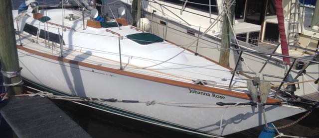
Below is a old photo of the forward hatch. When I obtained Johanna Rose, a C&C Landfall 38, the forward hatch above the V-berth was the only hatch which was not leaking (that much).  It was in rather ruff shape.  The lens was crazed, the hatch seal replaced by several globbed-up beads of a silicone by the previous owner.  And while it was a mess, it was still functional, but more importantly, most of the time it was covered by a nice custom-made sunbrella hatch cover.   The replacement of this hatch was more complicated than the others due to embedded seals in the lens. As seen below, the hatch has access knobs for opening the hatch on deck.    These knobs connect to a shaft handles below, so that turning the knobs also turns the handles allowing for the hatch to open. 

The old Atkins & Hoyle forward hatch


Removing lens and frame 

The hatch top was removed by tapping out the pressed in hinge pin.  This hinge pin is long rod which is slightly wider at one end and threaded with an acorn nut on the other.  To remove, tap on the acorn nut end to free the pin from hinge, then remove the acros nut and slide out the pin.   The remaining hatch hole was covered by an old piece of plywood.  To make the cover weather proof, a gasket made from foam pipe insulation lined the hitch rim.   The plywood was secured from below by screwing a 2x4 board across the opening in the V-berth and into the plywood.  

While the hatch lens work was in progress, Hurricane Michael came.  Fortunately we were located 60 mile west of the storm eye and only experienced tropical storm winds and rain, but the temporary hatch cover survived and surprising did not leak. 


Temporary plywood hatch cover 

Weather gasket made from foam pipe
insulation. 


Preparing Johanna Rose to anchor out
for the storm.


Johanna Rose safe and sound the day after Hurricane Michael
Path of Hurricane Michel show our
location as a star with a blue dot due
north in the rain bands.


Remove old lens and clean frame

The top knobs are held in place with set bolts going through the stainless steel handle shaft.  Stainless steel bolts, aluminum, and 35 years in a marine environment ment the bolts were near permanently galled in place.  I followed the advise given on youtube and removed the knobs with a pipe wrench, shearing off the screws.  Once the knobs are off, the shaft handles can be removed.  Removing the old silicone sealant was a chore.  I tried some Re-Mov silicone remover, but the best way to remove the old sealant was by brute force with a wire wheel and drill.  It took a lot of heat and several applications of PB Blaster to remove the stainless lock pin.

While for previous lens work, new EDPM seals were glued to the frame using Silaprene Adhesive, this time Dow 795 was used.  The Dow 795 adheres the EDPM to the frame as good as the Silaprene, the only caveat being that Dow 795 take longer to cure.

Removing Silicone
Hatch frame with old sealant seal and
galled stainless lock pin.


Frame after silicone removal.
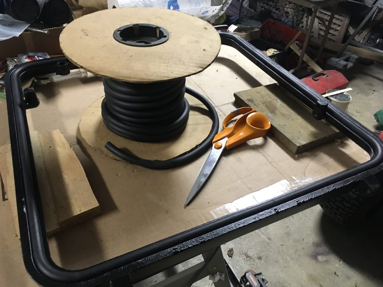
Installing new EDPM foam cord seal


Fabricating The New Acrylic Len

Fabricating the new acrylic lens was similar to the earlier work posted.  A table saw was used to cut the acrylic to square dimensions whereas the rounded edges were cut on a band saw.  Final clean up of the edges were done using a sander.  Great care was taken to  align and cut the shaft hole.  While the seal and recess holes can be cut using Forstner bits, care and much patiences must be taken so as not to creak the acrylic.  A better solution is to precisely machine the seal and recess holes.  SKF Dual Lip with Spring Rotary Shaft Seals were purchased from McMaster-Carr (item # 40J914).  These seals have dimensions: 1/2" ID, 1" OD, 1/4" T (SKF # 4985).    The seals were pressed in place by clamping.


Machined hole and recess with seal


Installed seal


Seals were installed by using
a clamp to press in place.


Hatch Hardware Work


Handle showing nylon spacers
and plastic spacer tube.
Epoxy painting the knobs


Teflon spacer

New plastic spacers were made
from Teflon  


The knobs were secured
using new SS bolts and
tap threading the SS shaft

The teflon tubes were reused but only
along the inner knob surface.


Final Installation 

Black Dow 795 sealant was used to bed the new lens into the hatch frame. This was done with the frame attached back on the boat.  A dry fit was performed taking care to adjust the spacers for proper hatch handle locking. The final step was to bed the lens with the sealant.   Prior to lens placement, a good sized bead of sealant was placed in the lower edge of the hatch frame.  The lens was then bedded in the frame and additional sealant was added between the outer lens edge and the frame.  Immediately  afterwards, the excess sealant was cleaned of and all tape and protective covering removed.  A weight was added on the lens and the Dow 795 was left to cure.

Dry fit of hatch lens and hardware before sealing


Hatch lens weighted down during the curing of the Dow 795


Finished Hatch

Completed lens replacement


Replacing the Companionway Sliding Hatch


While we all try to avoid stepping on the Companionway hatch, at some time or another we end up stepping on it.  I have done this inadvertently a few times in the past, but I always tried to take care not to put to much force on it.  Well in August 2018, during a rush job of putting on the mainsail cover, I stepped on and cracked the top acrylic hatch.   It was initially a small crack, but after push and playing with it, the crack grew somewhat longer.   In the same rush a temporarily kludged fix was done using foil tape to "mend" and seal the long crack.  It stayed this way for about a month while I thought of ways to replace the acrylic, explored types of acrylics and alternatives,  estimated the costs, and finally found the motivation to just replace it.    

Original sliding hatch was constructed from 3/8" smoked
acrylic.  


Material Choice

I had every intention of purchasing a piece of  3/8" x 28" x 36" Transparent Grey Smoked Plexiglass. The cost for this material was reasonable cheap (on the order of  $100 plus shipping).  Instead,  I used a piece of clear 3/8" acrylic which was given to me some time back.  The problem with the acrylic (and the reason it was free) was that the protective paper was old, dried out, and did not easily peel off.  A trick I came across many years ago, was to soak the protective paper with isopropyl alcohol.  I found that placing and soaking paper towels on top of the protective paper allowed for a good solid soaking.  A plastic sheet (split open Hefty) was used to keep the alcohol from evaporating too quickly.   After about 30 minutes or so the protective paper would come off with little effort.


Removal and installation of a temporary sliding hatch

A temporary sliding hatch was constructed from 1/4"
exterior plywood.  A small 1"x2" wood strip was
added ,in a similar fashion to the original slider, to
which the locking hasp was attached.   
Since the old hatch was needed to pattern a replacement, a simple temporary sliding hatch was fabricated out of plywood and a 1" x 3" board.   This rather simple design functioned quite well as a sliding hatch.  Even a lock hasp was installed so that the hatch could be locked using the original locking set up.

The removal of the sliding hatch requires removal of the backstay traveler cross bar.  After its removal and removal of the hatch cover screws, the hatch cover simply lifts out and the sliding hatch is free to remove.


Cracked slider with temporary taped repair. The
side Aluminum angle rails, teak top handle, teak
bottom board, and teak slide stop have been
removed.


Fabrication

Clear 3/8" acrylic was sanded on both top and bottom faces to
provide a frosted appearance.
A table saw was used to cut the acrylic to the width and overall length matching the original hatch dimensions.   The original hatch used long aluminum L-bracket for sliding on top of the frame of the companionway.  Each bracket was held on with 6 flat head machine screws with thin hex nuts on top.  The old brackets were removed and the bolt holes were  transferred to the new acrylic.  VERY IMPORTANT!  Use plastic drill bits to drill the holes in acrylic or you will most/very likely crack the acrylic.  After drilling the matching holes, the L-brackets were reattached using a little marine sealant (butyl would be better) and the two surfaces of the acrylic were lightly sanded with 320 grit paper to create a frosted look.  The teak top strip and bottom  teak brace were reinstalled as it was on the original hatch.  Not seen in any of the photos is the back stop block.  The stopping block is a teak strip attached on the underside at the back end of the hatch.  It is attached to the acrylic using flat head wood screws.  A saber saw was used to round the front corners.  And finally, all edges were rounded smooth using an orbital sander.


Dry fit of sliding hatch components.  The teak bottom board is
secured to the acrylic by 5 flathead screws flush to the acrylic
surface.  These flathead  screws are covered by the teak slide
handle with an additional 3 screws securing the handle to the
bottom board.


New sliding hatch installed.


Final installation

The final installation was simply the reverse of the removal.  While the original intention was to use a piece of transparent smoked acrylic, the clear/frosted design looks smart-fully pleasing. In the end, the cost was under a few dollars as all of the materials were laying around save for a few stainless steel machine screws and nuts.


Sunday, August 12, 2018

Stemhead Bow Roller Replacement


Broken Stemhead Bow Roller

A Broken stemhead was noticed during a routine inspection of the forestay toggles.  The stemhead exhibited two long crakes between the mounting bolts on one side and the center forestay/chainplate mounts on the other. This effectively meant that  rigging was only secured by half of the bolts, but worst, the support was through an uneven load.   If left alone, the forestay would likely tear itself out causing all kinds of havoc.


Close view of crack along the headstay
attachment. 

Crack along right set of bolts


Old Deck/Hull Attachment Bolts

Disconnecting the headstay and the roller furler was straight forward.  Removing the 8 mounting bolts holding the stemhead bow roller to the hull/deck was not so easy.  Access to the mounting nuts located at the bow tip is through the chain locker.  There is inadequate space for using a ratchet socket and even little space for turning a wrench.  It took nearly 4 hours to remove the 8 bolts using a 1/2" flexing ratcheting wrench for all but two bolts.  The box end of the wrench did not fit on 2 of the nuts as the nuts were too close to the hull, these nuts were removed using the open wrench end at a rate of 1/6th turn at a time.    Once all nuts were removed, the stemhead bow roller was easy to lift out. 


Stemhead mounting bolts access via the anchor locker.


Securing the roller furler with a seat
cousin at the hull and lashing near toe
rail, up on a side shroud, and at the lower 
spreader.   A temporary (i.e. several weeks) 
mast support was  done with a removable forestay
and two halyards connected to the bow cleats.


Freeing the stemhead bow roller.
Another view of the old stemhead bow roller.


 New Stemhead Bow Roller Design

I found a company online which advertises the fabrication of custom stemheads.  While the products descriptions were nice and professional, the quoted price for a simple single bow roller stemhead was $1,800-$2,000.    I chose to design my own stemhead bow roller, and I was fortunate and very grateful to have the help from a friend in fabricating the design.    The design uses a 1/2" thick  316 Stainless Steel, all 316 Stainless bolts and hardware, and a commercially available bow roller and bow chocks.   A baseplate thickness of 1/4" and 3/8" were considered, but opted for 1/2" plate as it make a more robust design.  The added thickness also allows more secure beveled mounting of the underside bolts and for tapping and threading the bow roller attachment.  A Windline model AR-3 was used for the bow roller which is rated for anchors up to 60 lbs.  For bow chocks,  Schaefer XCL model 60-50 were used.  These bow chocks are secured from underneath the base plate with flush flat head bolts giving the appearance of a nice custom look.  The center chainplate mounting brackets were also bolted from the plate bottom with 4 bolts tapped into each bracket side.  These bolts were thread locked with Loctit 421 and sealed with Loctite PL Marine sealant.  The new design extends the anchor roller out an additional 5 inches but maintains the same winch chain centerline alignment.  This design include space to allow for the addition of a second anchor roller if future needs dictate, but currently plans are leading towards adding a padeye for external asym downhaul  block attachment.   The bow chocks were aligned centered to the chainplate clevis pin hole similar to the original.  The cost in added weight of the new design is an extra 17 lbs compared to the old stemhead bow roller.  This is a small amount compared to my 44 lbs Vulcan and 150' of 5/16" HT G4 chain. 

Before finalizing the design dimensions, a plywood template was made.  The original mounting holes were transferred from the old stemhead and a test fit on the vessel confirmed all dimensions and fitting.  In mounting the new stemhead, nearly a whole tube of Loctit PL Marine was used, much of the sealant was needed to fill a void right at the bow tip where the same amount of old sealant was removed.  The outside seal between the bottom of the new stemhead and the hull topside was made using bead of white Dow 795 silicone building sealant.  


New Stemhead design plan. Base plate is made from 1/2" thick  316 Stainless Steel plate.   The
new design extends the anchor roller by an additional 5 inches but maintains the same winch
centerline alignment.  The design include space to allow for the addition of a second anchor
roller. 

Material List


  • Base plate
    • 316 Stainless Steel plate  (Online Metals)
      • 316 1/2” x 12-3/4” x 17-3/4"      
        • includes material for stay mount brackets
    • Mounting Hardware (McMaster-Carr)
      •  Forestay brackets
        • 316 Stainless Steel Hex Drive Flat Head Screw, 5/16"-18, 1" length 
          •  quantity : 8  
      • Mounting bolts  
        • quantity: 8  
          • 316 Stainless Steel Hex Drive Flat Head Screw, 5/16"-18, 3" length
          • 316 Stainless Steel Hex Nut, 5/16"-18
          • 316 Stainless Steel Lock Washer, 5/16"-18
          • 316 Stainless Steel Washer, Oversized, 5/16" Screw Size, 0.344" ID
            • two bolts used standard 316 Stainless Steel Washers
      • Bow chock bolts
        • 316 Stainless Steel Hex Drive Flat Head Screw,  M12 x 1.75mm Thread, 30mm Long
          • quantity: 4
      • Bow roller bolts
        • 316 Stainless Steel Button Head Hex Drive Screws 3/8"-16 3/4"
          • quantity: 5
          • bolts shortened to 5/8"
    • Bow Chocks 
      • Schaefer XCL Model 60-50 (Marui Pro)
        • Bow Roller
          • Windline Model AR-3  (Ebay)
            • Bolt thread lock & sealing
              • Loctite 241 thread lock
              • Loctite PL Marine FC adhesive sealant  (a Polyether like 3M 4000UV)
              • Dow 795 Sealant, white


             A plywood prototype was constructed with bolt holes transferred
            from the original stemhead to test mounting and finalize design.

            Old stemhead next to new stemhead. The new designs extends
            the anchor roller an additional 5".  


            Mounting of the new stemhead bow roller.


            New stemhead bow roller with forestay rigged in place.
            New stemhead with anchor. A 316T stainless steel boom loop
            was added to function as an anchor containment loop.

            New stemhead with anchor