
Isolation of Galvanic Voltages (A self inflicted problem)
The main purpose of Galvanic Isolator is to provide isolation from galvanic voltages which result from bonding the AC and DC grounds. The reason for connecting the AC & DC grounds is to provide an Effective Ground-Fault Current Path from the DC ground to the AC ground.
But in principle, the AC to DC ground connection, and thus a Galvanic Isolator, should not be needed since GFCI( also called ELCI or RCD) protection should be used for all vessel AC loads. This can be accomplished for the whole vessels by installing an ELCI Main Circuit Breaker such as a BlueSeas model 3106100. In fact, the ABYC E-11 now requires all new vessels to have such a device. An ELCI/GFCI detects ground-faults and disables the circuit. Disabling a ground-faulted device by eliminating the power source is much safer than just providing a safe effective ground-fault current path.
Many small and older sailboats do not suffer from galvanic corrosion. The reason is that these vessels often do not have their AC & DC grounds connected. If a vessel has only a few AC outlets, then the likelihood of an AC to DC ground-fault is rather small. Typically on these vessels only a battery charger is interfaced to both AC and DC power systems. But any decent marine battery charger should be built to ABYC / UL 1236 standards which require isolation of AC & DC (i.e., Don't use cheap chargers). In any case, one GFCI outlet can protect the whole boat from ground faults making the vessel ground fault safe without the necessity of connecting DC and AC grounds.
So why connect the AC and DC grounds if ELCI/GFCI protects the vessel from ground faults? To be honest, there is no good reason. Famed boat guru Nigel Calder advocates against connecting AC and DC grounds. And new standards no longer require AC to DC ground connections when the "whole-craft" is ELCI protected. See IOS 13297 excerpt below.
A possible reason given is because of the "other guy". That is, electrical problems which originate external to (i.e. outside) one's vessel. These are problems due to faulty or incorrectly wired shore power or poor/faulty electrical systems on neighboring vessels. While GFCIs can protect a vessel from self ground faults, unfortunately a GFCI will not protect against external faults. No one wants to work on an engine and end up being the conduit to ground for a stray neighboring current. In this case, an AC to DC ground connection can provide protection (unless one is removing the engine ground in which case an AC to DC ground connection could be harmful).
Given all of this, it does not make much sense to spend a lot of money on a Galvanic Isolator. But rather, invest in an ELCI Main Circuit Breaker. These devices cost less than most Galvanic Isolators. If one does connect the AC & DC grounds then one should make this connector through a basic Galvanic Isolator like a Yandina (or DYI device like the one described below) since this type of connection, opposed to cutting and inserting into the AC "green" ground, does not compromise the vessel AC ground fault safety, that is a fail-safe connection. A good DYI Galvanic Isolator is easy to make and cost relatively very little (~$10). The DYI Galvanic Isolator shown below was made with free scrap material costing only $5.60 for the rectifiers.

Components
 |
| Bridge Rectifier |
- (2) Bridge Rectifiers
- 50A 1000V Metal Case Bridge Rectifier with Heatsink
- KBPC5010
- Amazon: $2.80 each w/ free shipping
- length of green wire & solder
- (2) crimp-on ring connectors
- (2) 1/4-20 SS bolts for wire terminal ends
Component & Circuit Description
First grab the rectifier and identify the "+" terminal. This terminal is marked with a "+" and is oriented at right angles to the other three. Diagonally across from the "+" terminal is the "-" terminal. The other two terminals are the AC terminals sometimes marked with a "~". The "~" terminals are not used and are often best cut off to make it easier for making wire connections and eliminate installation mix ups or later shorting out.
Below is the circuit diagram. Shown are the two rectifiers connect by wires. The arrows show the direction of current flow. Each rectifier connection only lets current to flow in one direction. The two opposite rectifiers allow current flow in alternating direction (i.e. AC). But current can only flow when the voltage exceeds ~1.2 Volts (twice the forward bias voltage of single diode). Since galvanic voltages are well below 1 Volt, galvanic DC currents are blocked whereas AC currents are not.
Circuit Assembly
The diagram shows the input and output green wire connected in the middle of a wire connection of the (+) & (-) of each rectifier. In fact, it is easy to use one long wire (~ 1ft) on each connection. A stripped wire end can be tightly wrapped through and around the (-) terminal while the (+) terminal connection can be made by stripping out an inch of insulation from the wire just a little way from the (-) end (without cutting the wire) and wrap this bare wire tightly around the (+) terminal leading remaining wire out. To further secure the mechanical connection, the wire can be soldered at the terminals. Alternatively, crimped spade connector connections should also work fine for making wire connections.
 |
| Circuit diagram: The arrows show the direction of current flow. Each rectifier connection only lets current to flow in one direction. The two opposite rectifiers allow current flow in alternating direction (i.e. AC). But current can only flow when the voltage exceeds ~1.2 Volts (twice the forward bias voltage of diode). Since galvanic voltages are well below 1 Volt, galvanic DC currents are blocked whereas AC c currents are not. |
Making a simple housing container
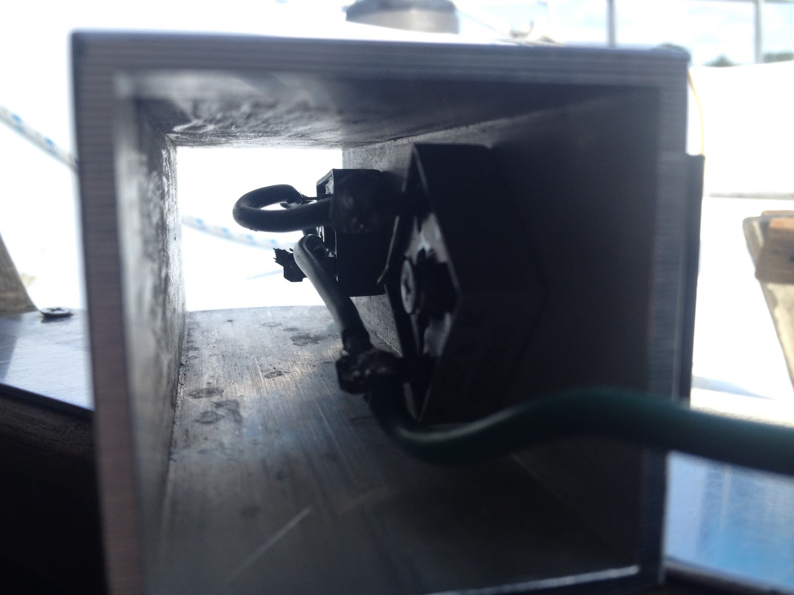


With the galvanic isolator circuit complete, a simple housing box can be fabricated using a scrap piece of square aluminum tube. Each rectifier can be bolted to the inside and to the heat sink on the outside. The green wires can be led out the ends and through a simple end caps made of HDPE. A bolt can be added top each end cap to form connection terminals, and a crimped on ring connection can be added to the trimmed green wire ends and connected the end bolt terminal. Alternatively, one could use a prefab housing box or even a simple piece of round tube or right angle extruded aluminum.
Aluminum allows for efficient heat transfer. But normal operation does not generate heat. Heat is only generated if there is an actual ground fault. In principle, the circuit can operate at currents higher than a 30AMP shore power supply. But one should also be using GFCI circuit protection which would cut the power if a ground fault exists.
 |
| DYI Galvanic Isolator prior to installation. |
First off, it is important to use a decent marine battery charger and not a cheap $10ish charger. All AC loads on a vessel should be GFCI protected, and even better use in addition, an ELCI Main Circuit Breaker in the main AC panel. Then install a Galvanic Isolator between the DC ground and the AC ground and not by cutting/installing in the AC green ground line. This arrangement provides redundant protection mainly via the total GFCI protection and additional safe guards of galvanic isolated AC/DC ground fault path while not breaking the wire or adding components in series to the AC ground fault line.

Extract from ISO13297
4.2 The protective conductor (AC Earth) shall be connected to the craft's d.c. negative ground (earth) as close as practicable to the battery (d.c.) negative terminal.
NOTE If an RCD (whole-craft residual current device) or an isolation transformer is installed in the main supply circuit of the a.c. system (see 8.2), the negative ground terminal of the d.c. system need not be connected to the a.c. shore ground
(protective conductor).
shorting the + to - tabs and using the AC terminals will achieve the same result, with one diode bridge.
ReplyDeleteYes, but using 2 bridges increases the capacity and provides redundancy/fail safe in case any one diode in a bridge fails. Also recall that a bridge costs is $3, so there is no savings.
DeleteGg
ReplyDeleteI had built an isolator using the the same kbpc5010 Bridges you used. However the voltage drop is 0.6 instead of 1.2. I checked the Bridges individually Lee with a tester and a battery and have the same results. The voltage drop is 0.3 at the first diode the AC faston and 0.6 at the second Plus faston. Any idea why?
ReplyDelete